WITRN W96Pro Portable Mini Fan Review & Teardown Analysis, Circuit Analysis
I recently bought a mini fan that can be controlled via Bluetooth, supports percentage speed adjustment, 18W fast charging, a 4800mAh battery (21700), and a USB-C port for input/output—so it can also be used as a power bank. In this article, we’ll tear it down and analyze its circuit.
Gotian F95D Mini Fan Teardown: https://blog.zeruns.com/archives/953.html
Other teardown articles: https://blog.zeruns.com/tag/拆解/
Teardown video: https://www.bilibili.com/video/BV1Gft56TEYr/
Product Specifications
- Product Name: SDF Software Customizable Smart Fan
- Model: W96Pro
- Motor Type: Sine Wave DC Brushless Motor
- Motor Drive Power: 10W (12W peak output)
- Battery Spec: 21700 Li-ion battery
- Supported Battery Type: 3.6V Li-ion (fully charged about 4.2V)
- Input Power: 18W Max
- Input Voltage: DC 5~12V
- Input Current: 1.5A@12V, 2A@9V, 3A@5V
- Input Fast Charge Protocols: PD, QC, FCP, AFC, DCP
- Main Unit Size: 150x110x40mm
Purchase Link (AFF): https://s.click.taobao.com/RYC0Mkj
Fan Appearance
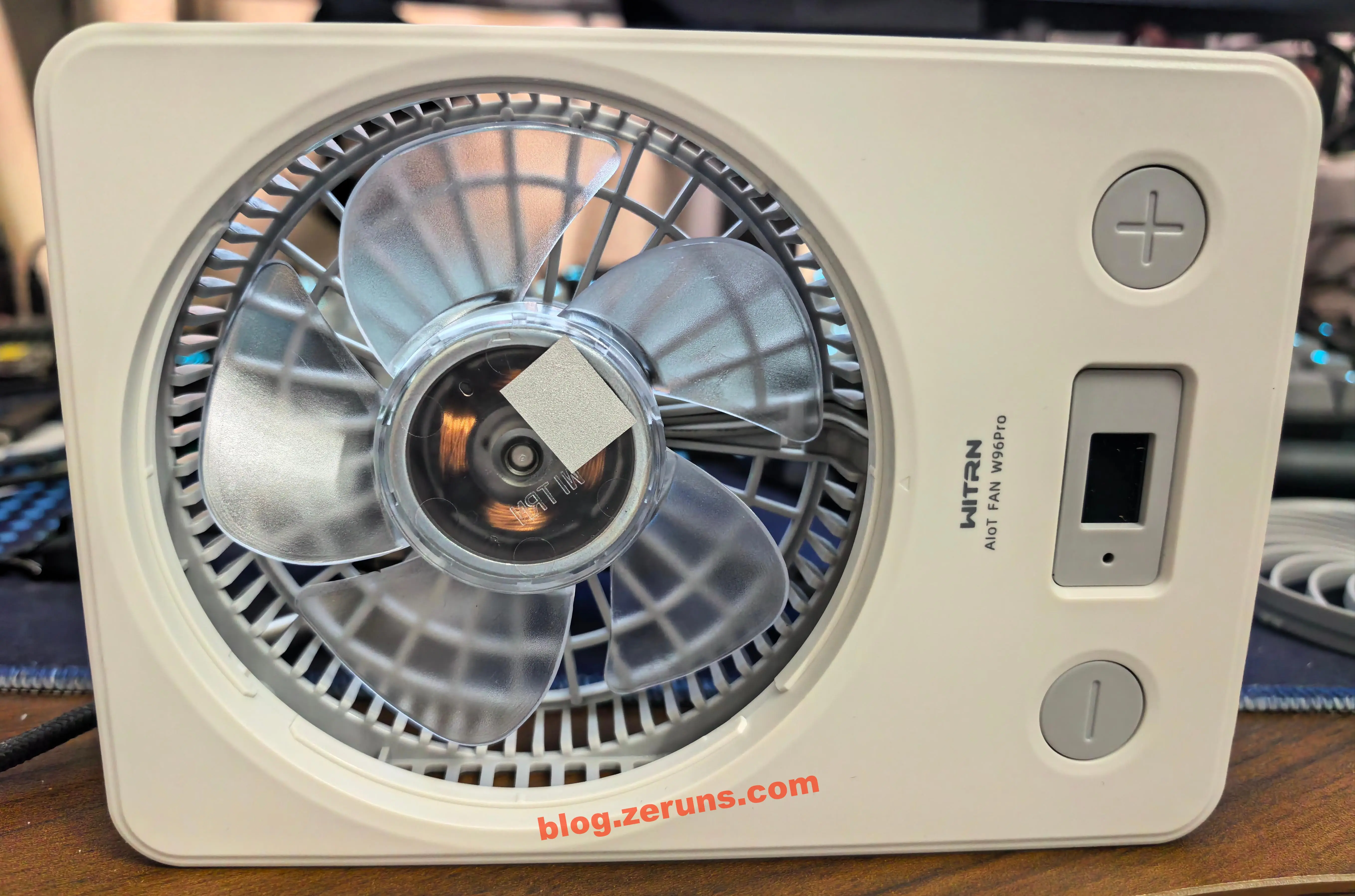
Front and back of the fan; front panel has two buttons:
- Left - Button: Press it once when the display is off to show battery percentage, then 0 gear; when the fan is running, short press decreases gear, long press decreases gear by 1% increments; double-tap while running sets a shutdown timer, double-tap again switches timer duration.
- Right + Button: Press once when sleeping to turn on to gear 1 (10%), press again to increase gear (default steps: 10%, 35%, 70%, 100%—these can be modified with the app); long press increases gear by 1% increments; double-tap activates natural wind mode.
There’s a Bluetooth indicator (blue light) and a 3-digit digital tube (white). Leftmost position only displays 1; rightmost has a lightning (green while charging) and % sign.
On the back is a label with specs (in Chinese and English):
- W96 Pro
- INPUT VOLTAGE: 5-12V
- 输入电压: 5-12V 输入电流: 2A
- INPUT CURRENT: 2A
- Do not put your finger or any other objects into the device to prevent injury and break down the device.
At the bottom back is the battery bay, supporting 21700 Li-ion batteries.

Right side: Type-C charging port, which is bidirectional—so the fan can act as a power bank. There’s a tamperproof label on a battery bay screw that says tampering is invalid.

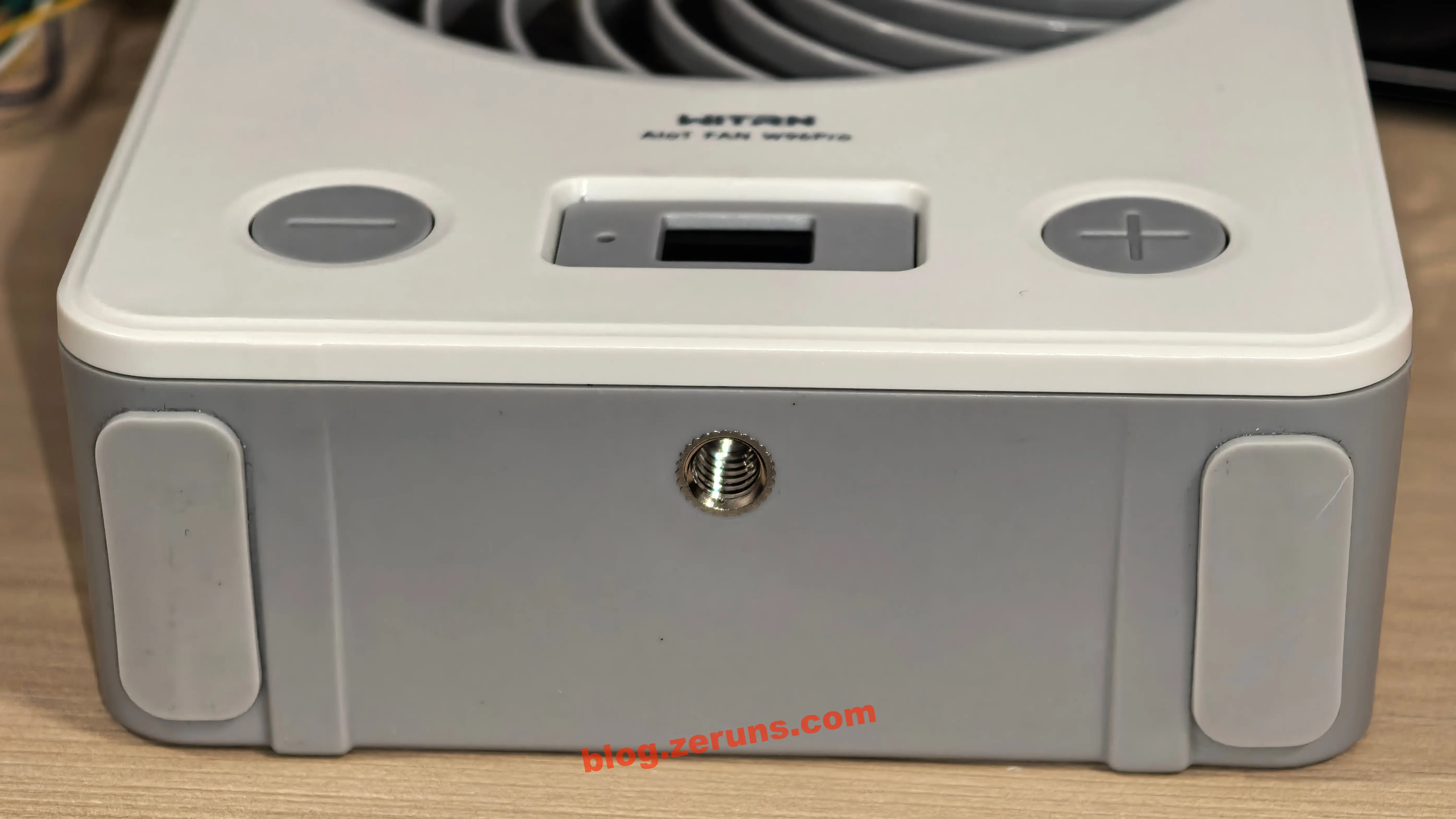
On the bottom is a 1/4-inch thread mount so you can fix the fan onto a tripod. The fan comes with two anti-slip pads (apply yourself; I put mine on the bottom).
When running at full speed, the fan can’t stand upright—it tips over. If you’re not using a tripod, I recommend attaching pads to the side and laying it on its side.
Charging Power and Heating Test
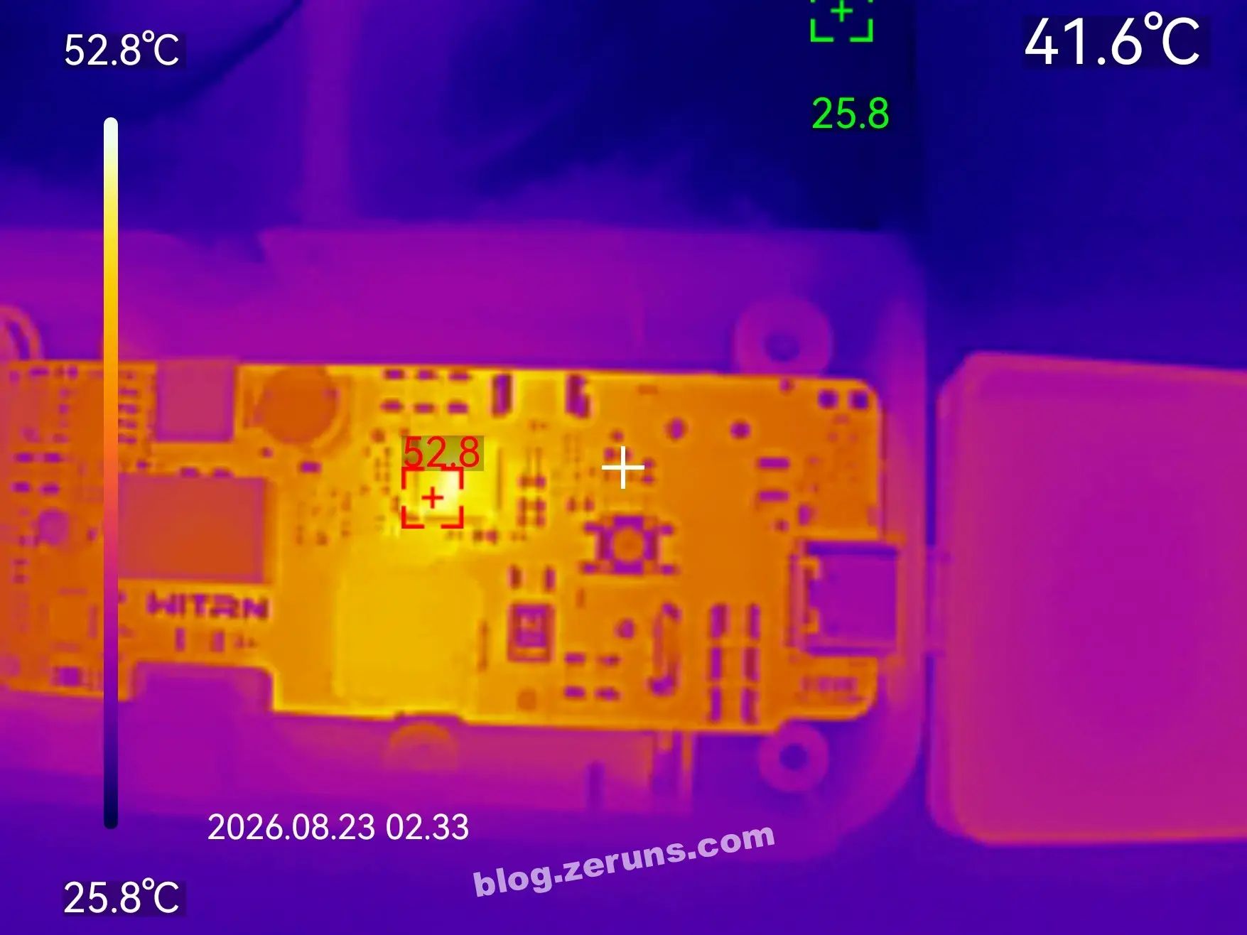
Charger used is 65W fast charger, PD protocol supported; fan battery at 59%, measured charging power around 17.5W, requesting 9V.

After 10 minutes charging, front PCB thermal image: ambient temp ~26°C, charging chip at ~52.8°C.
After running at 100% speed for 10 minutes, PCB thermal image: ambient ~26°C, boost chip for motor power at ~44.2°C.

RPM Test
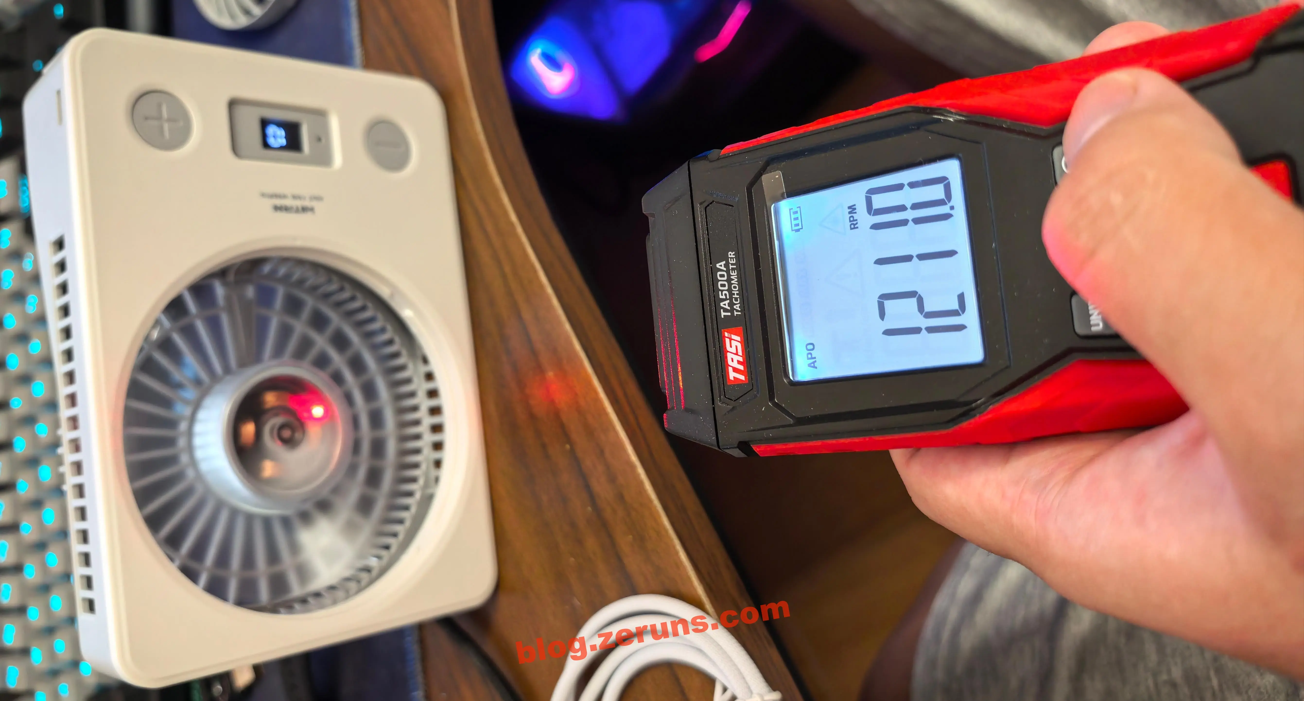
Used the TES TA500A Laser Tachometer to measure RPM. Attach reflective tape to the fan blades first.
Gear 1 (10%): 1211 RPM
Gear 2 (35%): 2390 RPM

Gear 3 (70%): 4173 RPM

Gear 4 (100%): 4893 RPM

Motor Power Test
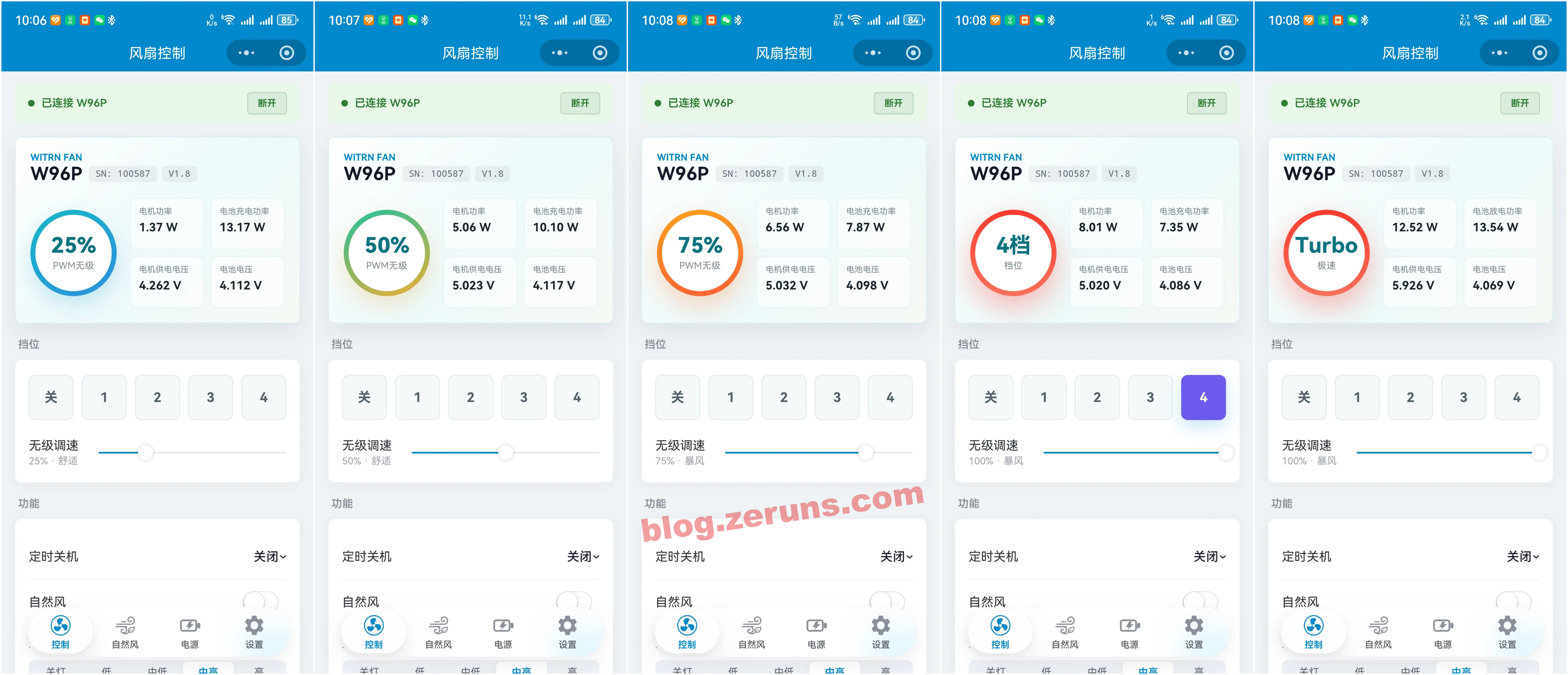
The following table’s data is read via the paired app in Bluetooth mode (compared to measurements by millivolt range with a multimeter across the motor sense resistor, app data is close enough to those from hardware).
| Gear | Motor Power | Motor Voltage |
|---|---|---|
| 25% | 1.37 W | 4.26 V |
| 50% | 5.06 W | 5.00 V |
| 75% | 6.56 W | 5.00 V |
| 100% | 8.01 W | 5.00 V |
| Turbo | 12.52 W | 5.90 V |
Motor is powered by a boost DC-DC chip; below 50% speed, voltage is 4.2V; at 50% and above, it’s 5V; Turbo is 5.9V.
Fast-Charge Output Test
Used RK-X3 Pro Fast Charge Tester and WITRN C5 Tester to check supported fast-charge protocols on the C port: supports PD22W, SCP25W, QC, FCP, AFC, etc.

The C port can charge a Huawei Pura70Pro+ at about 15W (PD3.0 18W, 9V requested).

Companion Mini-App
The companion app is split over four pages: Control, Natural Wind, Power, and Settings.
On control page, four parameters can be displayed in the top card. Available data includes PWM, shutdown timer, battery %, battery voltage, battery current, battery power, configured battery capacity, mainboard temperature (shows 0 on this model), charge/discharge status, VBUS voltage/current/power, charging chip temperature, motor current, motor voltage, motor power, motor status, etc.
You can control fan gear, adjust in percentages, set auto-shutdown, adjust display brightness, and so on.

Natural wind settings let you set the curve for “natural wind” mode.

Power status page shows all battery stats and allows you to set battery capacity (for coulomb counting), enables/disables certain fast charge protocols, and configures request/output voltage for charging protocols.
Note: There seems to be a bug in the firmware or app—new units sometimes have output compatibility issues (only some devices like my Huawei Mate70Pro+ and Pura70Pro+ can trigger fast charge; many others can’t). Using a WITRN CC meter also shows no protocol detection. Even when all protocols are enabled in “compatible mode,” issue persists. But after switching to “Expert Mode” and changing “Type-C Role” from Only Sink to DRP, everything works and protocols are detected fine.

Settings page lets you set RPM percent for each gear and update firmware.

Teardown
Remove six Phillips screws (four outside, two in battery bay, one under tamper-evident label), then detach the front panel. The motor has four stator windings—likely a 2-phase BLDC, maybe single-phase; to confirm, you’d need to remove the rotor and inspect the PCB and winding wires. Wires are 3P from the board to the motor.

Seen from the side, the motor has an integrated driver, just like a brushless PC fan—but W96Pro claims “sine-wave drive,” which is higher-end. There are four windings; typically, sine-wave drives are for 3-phase, but two-phase can also use 90° offset sine. Without oscilloscope measurement, can’t confirm if it’s truly sine-wave, but it’s plausible.
Sine-wave BLDC advantages over regular BLDC:
- Smoother torque, less vibration: sinusoidal current is in phase with back-EMF;
- Lower noise: less electrical noise vs. square-wave due to no fast current steps/harmonics;
- Higher efficiency, less heat: lower losses;
- Good low-speed behavior: stable at low RPM;
- Finer speed adjustment via PWM + boost regulator;
- Downside: more complex algorithm, higher cost.

Battery is JOINSUN INR21700-48 cylindrical ternary (NCM 811) Li-ion, model 48C (digital/energy), 4800mAh/3.6V, 17.3Wh; size 21700 (~21x70mm, measured 21.7x70.8mm), 3C (CCC) spec logo.
JOINSUN INR21700-48C Key Specs:
- Positive: NCM 811
- Capacity: 4800mAh nominal (min. 4700), voltage 3.6V, energy 17.3Wh
- Charge: max voltage 4.2V, current 0.5C (2.4A), max 1C, cutoff 2.5V
- Discharge: continous 2C (9.6A), pulse 4C (19.2A)
- Resistance: ≤22mΩ; weight: ~69–71g
- Cycle: ≥400 cycles @2C/80% DOD/25°C, ≥500 cycles @1C
- Certifications: UL/FCC/CE/RoHS/IEC/CB/CCC/PSE/UN38.3/MSDS
- Applications: fans, power banks, small appliances, etc.

Back of PCB has through-hole battery contacts; marked “WITRN”; plenty of solder mask windows for thermal dissipation of fast charge/boost chips.
Board uses ENIG finish (vs. cheaper HASL). ENIG is flat, corrosion resistant, long shelf life, good welding and contact reliability.
A parallel 220μF/25V solid electrolytic cap on the lower right, right at C port input for energy storage/filtering.
At the battery bay is a piece of aluminum with thermal pads to transfer heat from the fast charging/boost chips to the whole plate.
Some flux residue near the 7-segment and LED through-hole pins, likely due to manual soldering and no cleaning.
Residue can lead to lower insulation resistance, leakage (esp. with moisture), maybe corrosion/whiskers in the extreme case. But, with modern no-clean flux, this is mostly cosmetic and not a real defect.
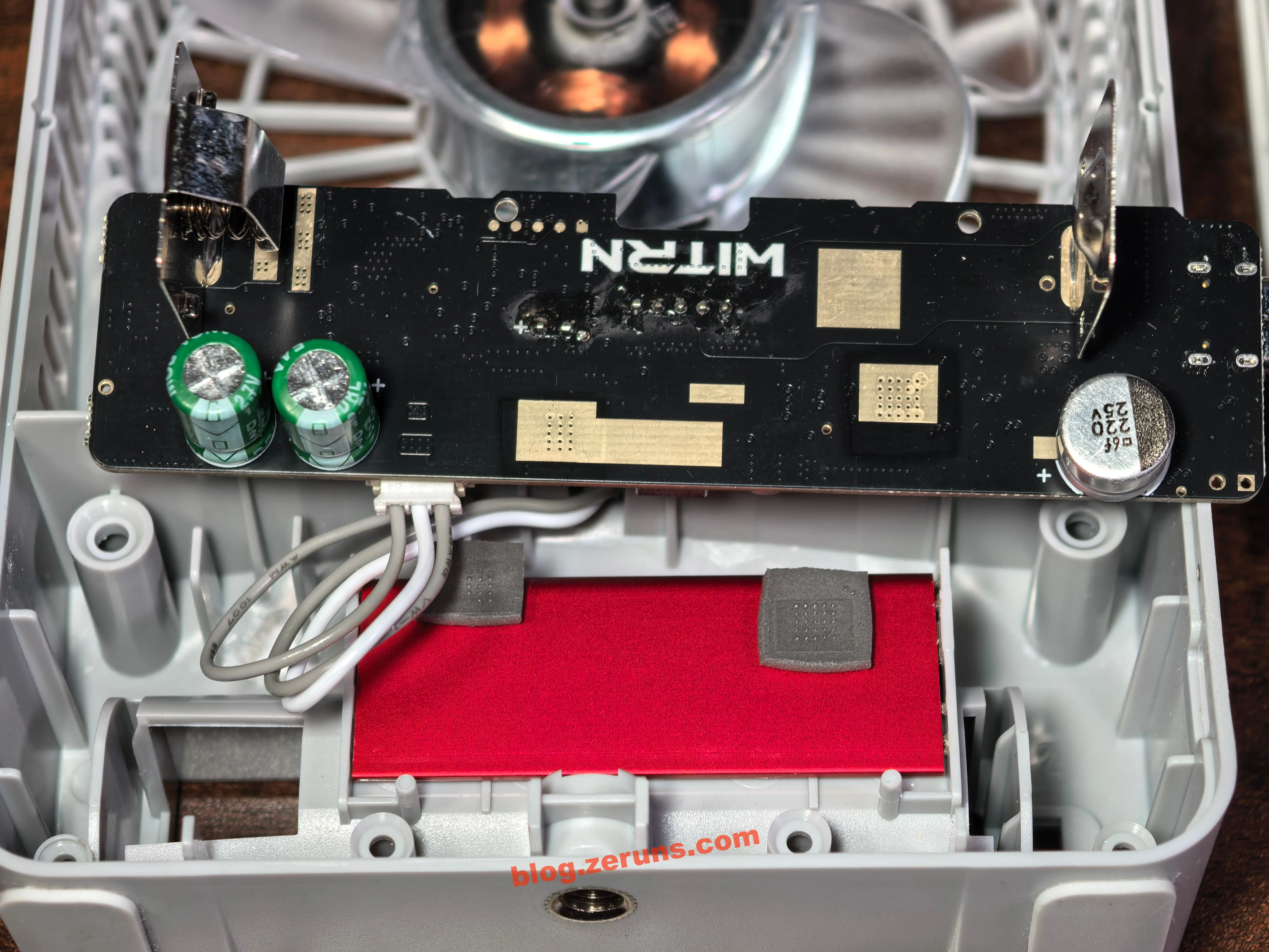
Back of the PCB, top left, two 1F/2.7V supercapacitors in series, connected across the battery.

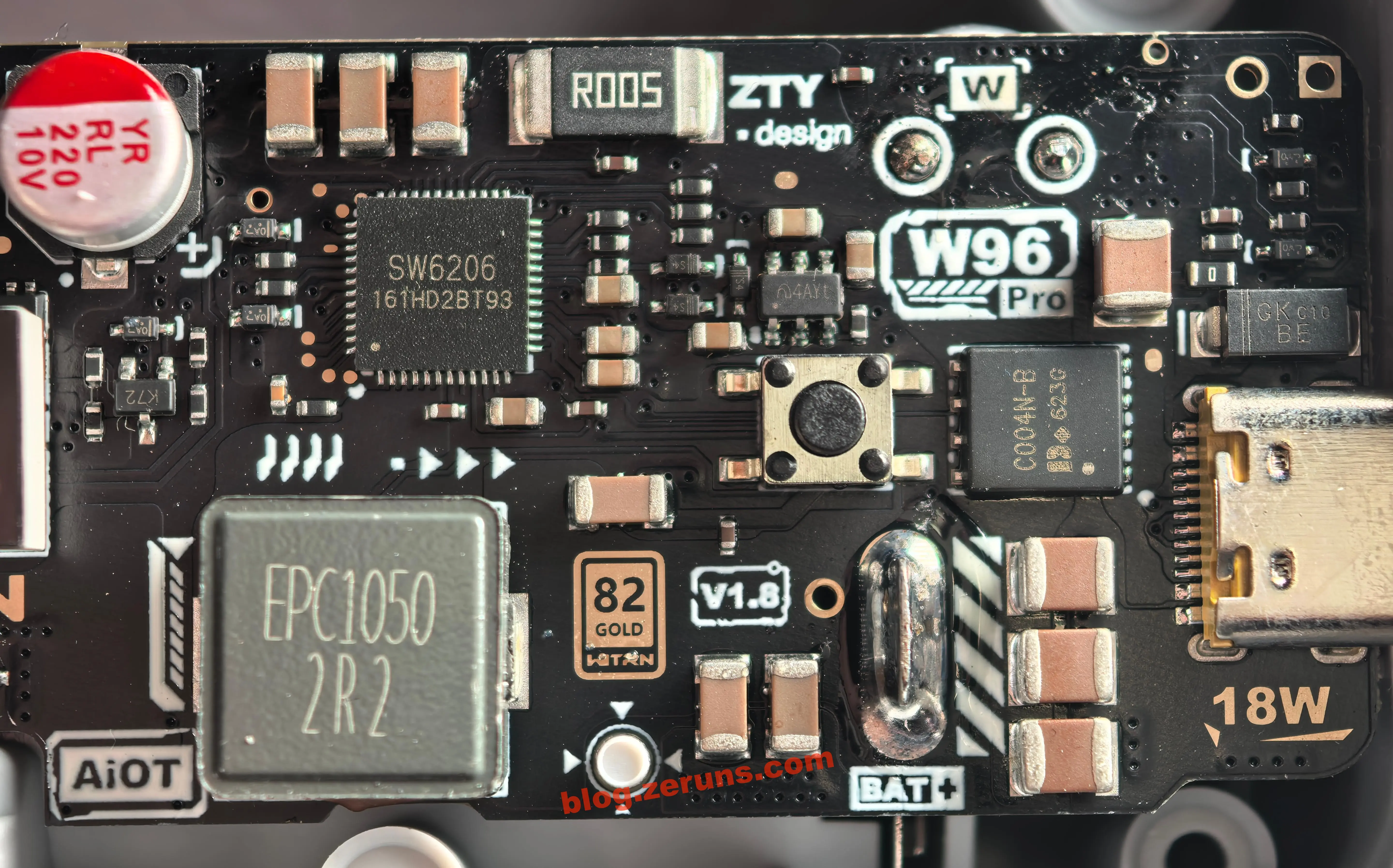
Front of PCB: model “W96 Pro”, version “V1.8”; by the Type-C port label: 18W. Blue SMD component below 7-segment is likely ceramic antenna for Bluetooth.
Motor socket looks to be PH2.0-3P: PWM control, GND, Vcc.

Charging circuit: power management IC is SW6206 from ISmartWare, multi-protocol bidirectional fast charge SoC. This is not the more common IP5353—SW6206 is bigger, higher integration (QFN48 6x6mm), dials input/output, battery charging, and fuel-gauging in one chip.
SW6206 Key Specs:
- Functions: multi-protocol bidirectional SoC, 5A high efficiency switching charger (96%), 22.5W boost (95%), fuel gauge, LED driver, Type-C logic
- Charging/discharging: 5A, supports 4.2/4.35/4.4/4.5V cells, NTC/JEITA thermal protection (not used in this board). 400kHz switching, just 2.2 µH inductor needed.
- Protocols: in PD3.0/2.0, AFC, FCP, SCP; out PPS/PD/QC4+/3/2/AFC/FCP/SCP
- I2C, GATEA/B/C/L pins
Below SW6206 is its coupled inductor, EPC1050-2R2, rated 22A, used for buck/boost.
EPC1050-2R2 Specs:
- STWEPC1050-2R2MT
- 2.2uH ±20%, DCR 5mΩ, Idc 22A, Isat 30A
The charge circuit’s max current is 5A; the 22A inductor leaves much margin, so this is well-built.
USB-C 5–12V goes through a C004N-B NMOS for power path switching into the charging circuit.
Above the SW6206 is a marked R005 (5mΩ, 2512), current- sense resistor for charging circuit.
MCU controls SW6206 via I2C, can read power data and set configuration.
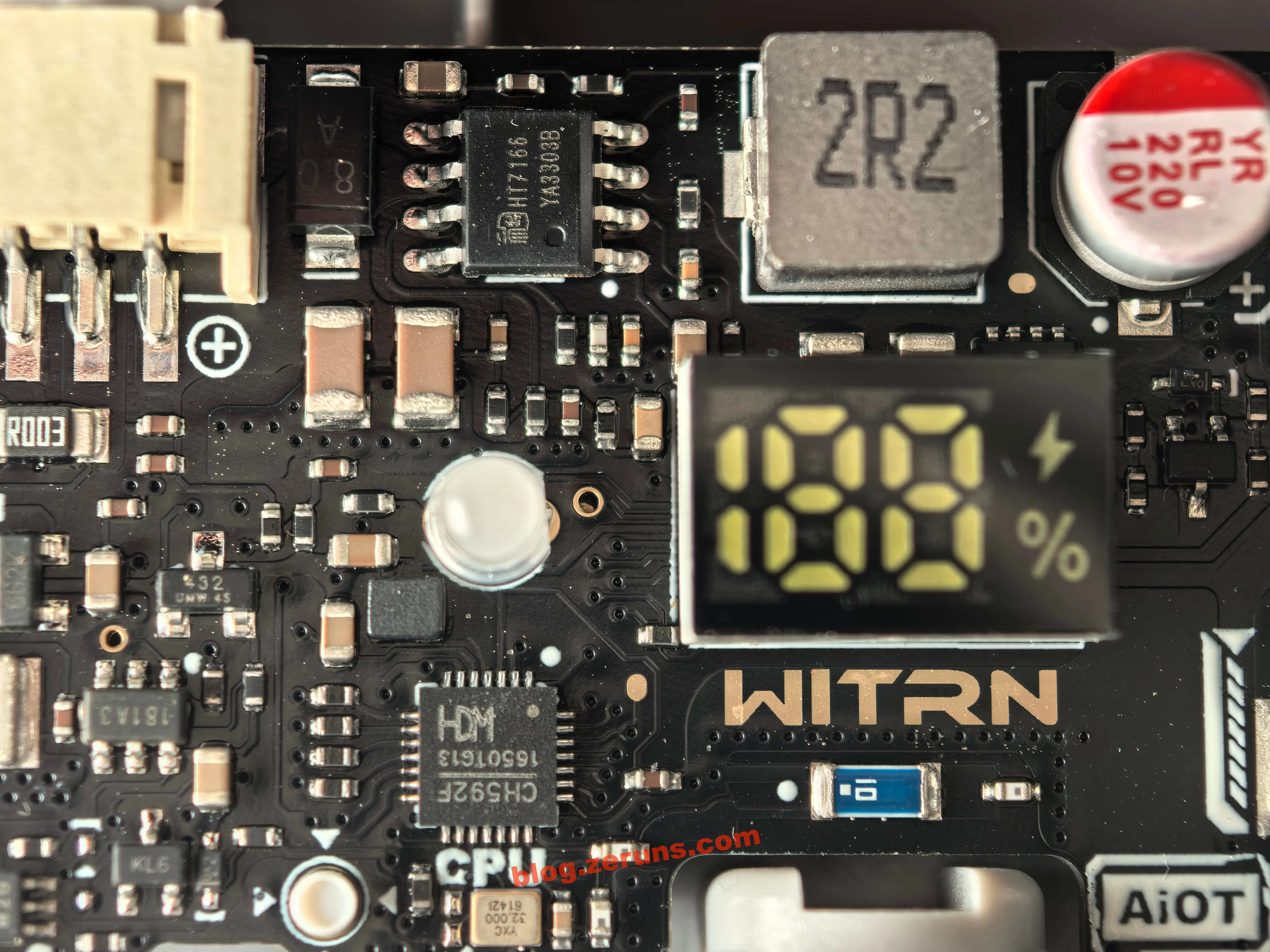
Next to the 7-segment LED: main MCU, CH592F (WCH, RISC-V BLE 5.4 SoC).
CH592F Key Specs:
- RISC-V4C 32bit, 80MHz, 512KB Flash (supports OTA upgrade), 26KB SRAM, 20 GPIO
- 2.4GHz transceiver, BLE 5.4, -95dBm sensitivity, +4.5dBm output
- LCD/7-segment driver, PWM, ADC, RTC, USB 2.0
- Integrated DC-DC, sleep current down to 0.3~2.5µA
- QFN28
The MCU handles: Bluetooth, display, buttons, wind/natural/timer/Turbo, outputs PWM, reads battery/currents, etc.
Below MCU is the clock (YXC 32MHz). Above the display is the motor boost supply—chip is HT7166 (Heroic), output voltage and enable are MCU-controlled; the boost output feeds the motor power, and only activates while fan is running. Under 50% speed: 4.2V, 50%+: 5V, Turbo: 5.9V.
HT7166 Specs:
- Heroic, 13V/10A fully integrated synchronous boost (ESOP-8-PP), 16mΩ power switch + 23mΩ rectifier
- VIN 2.7–13V, 600kHz, 4ms soft-start, 10A peak
- EN: <0.4V off, >1.5V on
- Protections: 14.2V OVP, UVLO (VIN2.4V), OTP; supports light load PFM
Wire diagram for motor and battery negative:
- Motor negative through R003 (3mΩ) sense resistor, amplified by 180A3 op-amp, to MCU ADC.
- Battery negative through protection, then R001 (1mΩ) sense resistor, amplified by 181A3, to MCU ADC; (coulomb counter integrates this in software).
INA180A3 (TI): +26V uni-direction current sense amp, SOT-23-5, 100V/V gain.
- CM input: -0.2V~+26V, BW~150kHz, input offset ≤±150µV
- Supply 2.7–5.5V, Iq ≤260µA
INA181A3 (TI): +26V bi-directional current sense amp, SOT-23-6, 100V/V, REF pin for direction.
- Similar specs; sees direction by REF >/< output
Note: These chips could be local alternatives given the silkscreen/market.
Above the 181A3 is a TL432 voltage reference, giving the 181A3 a stable zero-point.
TL432:
- Adjustable 2.5–36V shunt reference, ±0.5~2% accuracy, works as stable zero for bi-directional current detection.
In the upper left of the board: 300N03 NMOS, 30V30A, probably for soft-charging the supercaps to avoid inrush.
Battery protection uses DW01A + high-current MOS arrangement.
DW01A:
- Single cell Li-ion protection IC
- Overcharge: 4.3V, release 4.1V
- Overdischarge: 2.4V, release 3.0V
- Overcurrent: detect by MOS RDS, threshold 0.15V
- Short-circuit: detect 1.0~1.35V, delay 300~600µs
- 0V charge supported
- Quiescent: 3–6µA
SJM 18N035:
- NMOS, VDS 30V, ID 18A
Also a six-pin chip marked 2604 by the battery ground—unknown but likely related to protection, same as seen in Gotian F95D.
Another 6-pin chip marked M2B is also present—purpose unknown.

PWM Waveforms at Different Speeds
Oscilloscope test (DHO914S), fan PWM pin at 25% speed shows 19.6kHz, 63.1% duty.

50%: 19.6kHz, 74.9% duty.

75%: 19.6kHz, 87.8% duty.

100%: 100% (full on)

Summary
- Well-built circuit with generous margins.
- Versatile app, lots of metrics available.
- 18W charging power, doubles as portable charger.
- Decent airflow; max gear is noisy, but 35% is a good balance.
- At full speed, fan can’t stand upright—will tip.
- About 8 hours battery life at 35% gear, pretty good.
Recommended Reading
- Best Value / Cheap VPS & Cloud Server Recommendations: https://blog.zeruns.com/archives/383.html
- AI Large Model API Platforms Recommendations & Introduction: https://blog.zeruns.com/archives/947.html
- Minecraft Server Setup Tutorial: https://blog.zeruns.com/tag/mc/
- Hermes Agent Deployment Guide: https://blog.zeruns.com/archives/939.html
- Ugreen DXP4800Pro NAS Unboxing & Teardown: https://blog.zeruns.com/archives/949.html
- All About MQTT, IoT’s “Post Office”: https://blog.zeruns.com/archives/951.html
English Version of the Article: https://bbs.eeclub.top/t/topic/417?tl=en

